Sunday

Starting with OrCAD Layout

Before we can manufacture a PCB, we need to know about the footprints and other related terms. Footprints are the pin layout of the components that you are using. For a circuit to be manufactured properly, its footprint must be properly selected. We select footprints for the components, in Capture CIS itself. But we will be using Layout to select footprints. Let?s start now.

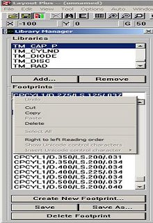
Start OrCAD Layout Plus from the programs menu. You may use OrCAD Layout or OrCAD Layout Engineer?s Edition in place of OrCAD Layout Plus. In Layout from the Tools menu, choose Library Manager. This will start a new window of Layout Plus with Library Manager loaded. Now find appropriate footprints for the components you use in circuit diagram. Some of the common libraries used for resistors and capacitors can be found in TM_AXIAL and TM_CAP_P sections. Similarly you can find footprints for other components if you explore the Library Manager a bit. Once you decide which footprint to use copy the name.

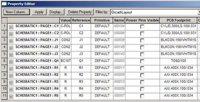
Still in OrCAD Capture CIS, press Control + A to select all the components and select Edit Properties. Now paste the footprint name in PCB Footprint column of the component you selected. After completing the above procedure for all components in the design, your Edit Properties window may look similar to one shown below. Once you complete all these steps then you can close Library Manager Window.

Now, its time to create a Netlist for our design. A netlist describes how different components in our design are interconnected and it also includes the PCB footprints. It is the input file for OrCAD Layout. We will create netlist in following steps.

  • Select OrCAD Project workspace and select from Tools menu, Create Netlist option. A dialog box as shown below will appear. Use the settings shown.
  • If the process completes without any errors, we can close OrCAD Capture CIS and start Layout Plus once again.
  • In Layout Plus, from the File Menu, choose New and you will be asked for a Technology Template File, use default.tch and when asked for a file to save board give a name and location where you want to save the board.
  • Now a new window with all components placed will be shown.

    We will discuss Component Placing and routing in the next segment.

Schematic Entry in OrCAD Capture

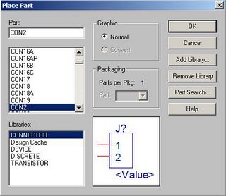
Now we are ready to enter the schematic in Capture CIS. We start by placing components in our design. Click on the icon and a dialog box appears.


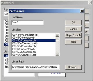
Select the component u want to place and place it on the workspace. If you can not find the component in the list shown, you can opt for Part Search… The best thing about part search is that you can use wild card characters such as *, in your search query. The parts search button appears like as shown in the next figure.

After you find the right component you can press the OK button and place the part in the workspace. When you place the part in workspace, OrCAD automatically names the component and will give you an option to place another one of the same kind. The cursor changes to one of the shape of the component you place. This is shown in the next figure.

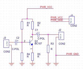
A small hint for moving around in OrCAD: use ‘I’ and ‘O’ to zoom in and out, respectively. ‘C’ will center the design at your cursor. ‘R’ will rotate a part. You can do these actions while in the middle of another action (e.g. while placing a part). You will also notice that each part has a value associated with it. You can change this by double-clicking the current value. In this manner you can give all your capacitors, resistors, etc. the appropriate values. The actual values don’t matter for your layout. It’s just for identification. Similarly place all the components in the workspace. Now use the wire tool to interconnect the different components in the workspace. The final result will look like:
Now its time to apply Design Rules Check (DRC). Select the project window and in the ToolsàDesign Rules Check? Apply design rules that you may want to check. Press OK button and OrCAD reports you any errors that are present in the design you just created. Remove those errors, if any, and continue. Now we can turn our attention to Layout.

Familiarizing OrCAD Capture

Before we begin…

OrCAD will create many files during the process of schematic entry and layout. To keep track of all these files can be a very annoying thing. So try to create a folder or subdirectory for each design you make. Putting everything in a common folder is not recommended.

Starting Capture...1…2…3

Be sure that you have installed OrCAD in your machine. Start the program by Clicking StartàProgramsàOrCAD Release àCapture CIS.

Next create a new project by clicking on FileàNewàProject. A dialog box appears as shown below:


A project workspace appears in a new window and is similar to one shown below:


The OrCAD project workspace consists of following sections:

Workspace: This is where you draw the schematics using various tools that are available. The area of workspace can be varied according to your needs. But if the project becomes a larger one, one should go for a multi-page schematic rather than going for a large workspace. This makes the project files look neat and well arranged. You can connect various components on different pages.
Toolbox: This is a bar at the right end of the workspace. This toolbar consists of shortcuts to various tools which you can use to create a schematic such as place component, interconnecting wires and bus etc.
Title Block: This is a box placed at the right bottom of the workspace. It is generally used to represent information about the design such as design name, name of designer, date & time etc.
Project Files: This is section which shows the files associated with active project. This section shows the design schematics you created any libraries you link, and some output files. Some menu items become active only if you select this window.
Session Log: Session Log shows a log of various activities you do in the project workspace. If some errors occur at any stage, a description of the error will be shown in this window.